Side Loaders

Left hand lifting lug
Side loading machine

This method of lifting containers incorporates transverse mounted hydraulic arms integral with a lorry chassis. It uses a pair of two legged slings each being attached to the hook of the lifting arms, whilst the bottom ends are attached to suitable lifting lugs, these should remain insitu if ever the slings become slack. This attribute is what makes the Preston Shoe ideally suitable for use with these machines.

Sling geometry when End Lifting

End Lifting sling angle range for Series 1 Containers.

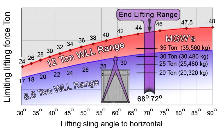
The sling geometry for single point end lifting is effective over a sling angle range between 68° and 72° typically 70°.
The sling arrangement determines the head room and normally they do not make contact with the end faces of container but lifting point may be below the roof of high cube units and with some machines, may make contact with the top end face of container.

In the diagram h is clearance between sling connection point and top of container
H is container height. (Range: 8ft to 9ft 6in)
 
For the sling assembly, the vertical distance T from aperture center (For Preston Lugs) to top lifting point in terms of sling angle α is:
T = ( P/2) tan α
Clearance h between lifting point and top of container is:
h = T + 68 - H
Angle
T
8ft
8ft 6in
9ft 6in
α
mm
2.44m
2.6m
2.9m
68°
2869
431
279
-27
70°
3177
739
586
281
72°
3550
1112
959
654
Clearance h above top of container.
Negative values are below top.
Chain lengths not given because of range of ancilliary devices available.

Limiting Gross Weights when END lifting ISO containers

The limiting Gross Weight (GW) is determined from sling angle and Working Load Limits (WLL) of 8.5 Ton or 12 Ton for these lugs. The GW must not be exceeded and these are shown here in general limiting lifting force diagrams for Side Lifting over the sling angle range 68° to 72°. Uniformly loaded containers give the maximum permissible GWs. For eccentric loading the results give LOWER limiting GW values owing to additional sling forces at the" heavy end". The GW for the two loading cases of uniform and eccentric payloads are given below and must either equal or preferably exceed the MGW of unit being lifted.
Limiting Gross Weights when sling forces are at their WLL over sling angle range 68° to 72° for Uniformly Loaded Containers

Gross Weights for uniform loading, lugs loaded to WLL

Level loading maintained

Sling angle range
Gross Weights
Central C of G
Angle
α
GW 8.5Ton
GW 12Ton
68°
31.52
44.50
70°
31.95
45.10
72°
32.34
45.65
Maximum GW over sling angle range
Gross Weights

Gross Weights for offset loading, lugs loaded to WLL

The Lifting Cycle describes the loading experienced during a lift, the nature of end lifting precludes an active "live load" component of any significance owing to slow hydraulic lifting system. When end lifting, the two arms normally operate independently enabling the container to be held level hence the problems of Tilt and Swing do not arise although any transverse eccentricity may result with lateral motion.

Eccentric Loading, Level lifting

Sling angle range
Gross Weights
Offset C of G
Angle
α
GW 8.5Ton
GW 12Ton
68°
28.66
40.50
70°
29.05
41.00
72°
29.40
41.50
Maximum GW over sling angle range
Gross Weights
These values are found from Equation 7
When lifting eccentrically loaded containers the limiting Gross Weight is always lower than for uniform loading.